On this page
On this page
Indicator lamps, DTR, RTS and Break
The Connection Settings group shows a row of indicator lamps: a TX/RX activity pair that flashes on traffic for every connection type, and — for serial connections only — the six control lines RTS, CTS, DTR, DSR, DCD and RI. The input lines (CTS, DSR, DCD, RI) show live levels while the port is open; some USB serial adapters do not report them. The row can be hidden with "Show TX/RX and control line indicators" on the settings dialog's Display page.
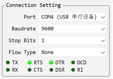
Directions are relative to the computer running the application (or its USB serial adapter):
| Lamp | Direction | Full name and meaning |
|---|---|---|
| CTS | Input | Clear To Send: the peer permits this computer to transmit. With RTS/CTS hardware flow control, transmission may pause while CTS is not asserted. |
| DSR | Input | Data Set Ready: the peer device or modem is ready. |
| DCD | Input | Data Carrier Detect: a modem has detected a valid carrier; non-modem equipment may also use it to indicate a valid link or connection. |
| RI | Input | Ring Indicator: a modem has detected an incoming ring; ordinary serial devices often leave it unused. |
| DTR | Output | Data Terminal Ready: this computer indicates that it is ready; some development boards repurpose it for reset or bootloader entry. |
| RTS | Output | Request To Send: this computer requests permission to transmit; the serial driver manages it when RTS/CTS hardware flow control is enabled. |
Three lamps are also controls:
- DTR / RTS: click the lamp to toggle the requested output level. These two lamps always show the requested level, so a port can be preconfigured before it is opened. RTS is clickable when flow control is
NoneorXON/XOFF. - TX: click to transmit a serial break condition (stretched to a minimum pulse so equipment recognises it), or press and hold for a longer break; the lamp turns amber and reads BRK while the line is held. Break needs an open port, is not a newline character and does not append
CRorLF.
DTR and RTS are serial control outputs, separate from the data bytes shown in Text or Hex mode, and are not available for TCP or UDP connections.
You can choose DTR and RTS before opening the port. The application applies those choices whenever it opens the port, including automatic reconnect and send-time reopen, and clears the physical outputs before a normal close. The requested levels can also be set on the Control Lines row of the settings dialog's Port page; they default to checked and are remembered across sessions, so boards that must not see DTR asserted on open only need to be configured once.
When RTS/CTS flow control is selected, the serial driver owns RTS: the RTS lamp shows a steady amber "taken over" state and clicking it does nothing. Do not use manual RTS as RS485 transmit-direction control unless the adapter and driver explicitly require it; most USB-to-RS485 adapters handle direction automatically.
Checked means logically asserted. The voltage seen at a connector may be inverted by an RS232 transceiver or USB adapter. DTR also resets or enters the bootloader on many MCU boards, so clear it before opening when the target must not be reset. For bootloader or recovery sequences, follow the device vendor's required DTR/RTS order and Break duration.